
CNC Busbar Punching Precision: Die Clearance, Coordinates, and Tooling Audits
In high-voltage switchgear and power distribution engineering, the physical quality of a copper busbar’s punched holes determines the long-term safety of bolted joints. Under-engineered hole clearances or inaccurate coordinates punching cause structural bottlenecks. Deformed copper plates lead to mechanical hot-spots, high contact resistance, and severe electrical arcing hazards inside electrical enclosures.
For B2B panel manufacturing plants, transition from manual templates to a dedicated automatic CNC punching and shearing workstation or a versatile 3-in-1 multi-station busbar processing machine is the primary method to secure mechanical coordinate accuracy and eliminate manufacturing defects.
This technical paper analyzes the parameters of precision CNC busbar punching, focusing on matching punch-and-die clearances, coordinates alignment, and proper tooling audit procedures.
The Mechanical Physics of Punching Red T2 Copper
High-conductivity red T2 copper is a highly ductile, non-ferrous metal. Under the high compressive tonnage of an industrial punch press, the copper undergoes three distinct mechanical deformation phases:
- Elastic Deformation: The punch makes contact with the copper plate, compressing the material within its elastic limits.
- Plastic Flow (Penetration): The punch penetrates the material, drawing the copper down into the die opening and creating a highly burnished, shiny band around the hole circumference.
- Shear Fracture: The internal shear stress of the copper exceeds its ultimate tensile strength. Micro-cracks initiate from the cutting edge of both the punch and the die, meeting to release the slug.

To ensure the hole walls are smooth, flat, and perpendicular, the punch cracks and die cracks must align precisely. This alignment is governed entirely by die clearance.
Tooling Clearance Ratios for T2 Copper
Die clearance is defined as the difference between the outer diameter of the punch and the inner diameter of the die cavity. It is represented as a percentage of the total sheet thickness ($t$).
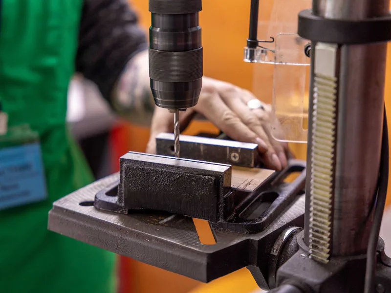
For red T2 copper busbars, we recommend the following engineering clearance metrics:
| Copper Thickness ($t$) | Total Clearance ($c$) | Punch Diameter (Example) | Die Diameter (Example) | Expected Burr Height |
|---|---|---|---|---|
| 3.0 mm | 8% ($c = 0.24\text{ mm}$) | 10.0 mm | 10.24 mm | < 0.03 mm |
| 5.0 mm | 8% ($c = 0.40\text{ mm}$) | 10.0 mm | 10.40 mm | < 0.05 mm |
| 8.0 mm | 10% ($c = 0.80\text{ mm}$) | 14.0 mm | 14.80 mm | < 0.08 mm |
| 10.0 mm | 10% ($c = 1.00\text{ mm}$) | 18.0 mm | 19.00 mm | < 0.10 mm |
| 12.0 mm | 12% ($c = 1.44\text{ mm}$) | 20.0 mm | 21.44 mm | < 0.12 mm |
The Danger of Mismatched Clearances
- Under-Clearance (< 6%): The fracture lines fail to meet. The material undergoes secondary shearing, which doubles the required tonnage, accelerates punch wear, and causes high heat buildup.
- Over-Clearance (> 14%): The fracture lines meet prematurely, causing the ductile copper to draw deep into the die opening. This results in heavy rollover edges, large taper angles, and severe, sharp burrs that violate international insulation standards.
Turret Multi-Punch Die Configurations
Modern CNC workstations utilize a multi-station turret indexing system to speed up operations. For high-volume switchgear plants, the turret is pre-loaded with standard dies, typically organized as:
- Round Punching Dies: For standard bolt sizes (M6, M8, M10, M12, M16).
- Oblong (Slot) Punching Dies: Essential to allow for thermal expansion adjustment in high-amp cabinets. Oblong holes must be punched with their long axis parallel to the copper extrusion direction to prevent structural tearing.
- Engraving / Marking Dies: Used for ISO 9001 part traceability tracking.
Preventing Slug Pulling
Ductile copper is highly prone to sticking. During the upward stroke of the punch, the cut slug can adhere to the punch face and pull up into the die cavity, blocking subsequent operations. To prevent this, professional CNC tooling integrates:
- Pneumatic Stripping Sleeves: Hardened steel sleeves that clamp the copper bar firmly against the die face before the punch withdraws.
- Spring-loaded Ejector Pins: Miniature pins embedded in the center of the punch face that mechanically push the slug away into the scrap bin.
3D Coordinate Alignment and Feed Margin Audit
To prevent the structural collapse of a copper busbar under high short-circuit electromagnetic forces, standard coordinate layout boundaries must be enforced:
- Edge Distance Rule: The minimum distance from the edge of any punched hole to the edge of the copper bar must exceed 1.5 times the copper thickness ($d \ge 1.5t$).
- Hole Spacing Rule: The distance between two adjacent punched holes must exceed 2 times the copper thickness ($s \ge 2t$).
- Bending Limit margin: Punched holes must remain outside the deformation zone of any subsequent bends. The minimum distance from a hole edge to a bend line must exceed 2.5 times the copper thickness plus the inner bending radius ($L \ge 2.5t + R$).
Using our integrated 3D nesting and layout software, these parameters are pre-programmed into the HMI, automatically preventing operator coordinate errors during production.
Precision Tooling Audits and Maintenance Checklist
To maintain long-term coordinates positioning accuracies of ±0.15mm and prevent production defects, factory managers should execute a rigorous tooling audit schedule:
- Every 5,000 Strikes: Inspect die cutting edges for micro-chipping. Clean copper dust residue from the stripper sleeve.
- Every 10,000 Strikes: Measure punch-head radius wear. Resharpen cutting faces (removing 0.05–0.10mm max) to maintain flat punch geography.
- Every 20,000 Strikes: Verify linear coordinates alignment on the servo feed guides. Check clamping pressure logs (minimum 1.2 MPa).
Engineering procurement teams are highly encouraged to request a custom feasibility tooling audit prior to ordering. Our engineering staff will review your panel CAD drawings to ensure your machine turret is pre-configured with the exact required die sizes and clearances.
Frequently Asked Questions (FAQs)
Why is correct die clearance so critical when punching high-conductivity T2 copper?
T2 red copper is highly ductile. Under-cleared dies cause high friction and fast punch wear, while over-cleared dies draw the copper into the gap, causing heavy deformation and extensive burrs. For 10mm copper, a standard B2B clearance of 8% to 10% of material thickness is specified.
How does the DHCNC-BP-60 coordinates positioning prevent sheet deformation?
The DHCNC-BP-60 utilizes heavy-duty pneumatic clamps driven by dual-axis closed-loop AC servo motors. These clamps secure the copper bar against hardened steel guide fences, maintaining coordinates accuracies of ±0.15mm and eliminating stress buckling.
DHCNC-BP-60 CNC Punching & Shearing Workstation
Discover details, parameters, standard dies packages, and factory quotes.