
Switchgear Panel Busbar Systems: Engineering Design, Splicing, and Compliance
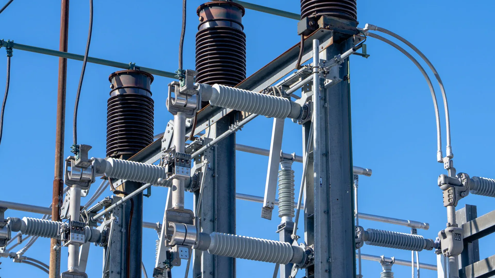
In mid-voltage (MV) and low-voltage (LV) electrical switchgear manufacturing, the layout of the copper busbar system represents the critical heart of power distribution. Sourcing and fabricating structural busbars require strict engineering controls. Design errors, incorrect spacing, or poorly punched joint connections will result in severe heat buildup, insulator degradation, and catastrophic short-circuit flashovers.
For B2B switchboard manufacturers, scaling up production from manual hydraulic tooling to a fully integrated automatic CNC punching and shearing center or a high-performance 3-in-1 multi-station busbar processor is essential to meet strict international standards and prevent costly operational faults.
This engineering guide examines the rules of low-voltage switchgear busbar layout design, bolted joint splicing, and international standard compliance.
Structural Creepage and Clearance Air Gaps (IEC 61439-1)
To ensure safety under high thermal loads and sudden overvoltage surges, designers must maintain standard air gaps and creepage distances between phase conductors and ground planes:
- Clearance Distance (Air Gap): The shortest physical distance in air between two active conductors. Under IEC 61439-1, a standard rated impulse withstand voltage ($U_{\text{imp}}$) of 8 kV requires a minimum air clearance gap of 8.0 mm.
- Creepage Distance (Surface Gap): The shortest distance along the surface of a solid insulation material between two conductors. For a typical rated insulation voltage ($Ui$) of 1,000 V AC in a Pollution Degree 3 environment, the minimum creepage distance over epoxy or glass-fiber supports is 14.0 mm.

Every hole punched or formed bend must maintain these spacing thresholds. Using a high-precision servo-hydraulic busbar bender with auto-springback compensation ensures that bent coordinates do not deviate from CAD specifications, preserving structural spacing limits.
Bolted Joint Splicing & Contact Resistance Optimization
The bolted overlap joint is the primary bottleneck in any high-amp busbar system. The contact resistance ($R_c$) of an overlap joint is governed by:
- Contact Area (Overlap Length): The standard B2B overlap rule is a 1:1 width ratio (e.g., an 80mm wide busbar must have an 80mm overlap joint).
- Interface Surface Flatness: Punching operations must produce clean, burr-free edges. Dull dies create raised edges that limit contact to the periphery of the hole, doubling contact resistance.
- Clamping Force (Torque Profile): High-conductivity red copper undergoes thermal expansion cycles. Joints must be bolted using high-tensile Grade 8.8 bolts combined with Belleville (conical) spring washers to maintain constant clamping pressure during temperature fluctuations.

Designers should follow standard torque specifications:
| Bolt Size | Metric Grade | Recommended Torque (N·m) | Clamping Force (kN) | Recommended Copper Thickness |
|---|---|---|---|---|
| M8 | Class 8.8 | 20 - 25 N·m | 15.6 kN | 3.0 mm - 5.0 mm |
| M10 | Class 8.8 | 40 - 45 N·m | 24.8 kN | 5.0 mm - 8.0 mm |
| M12 | Class 8.8 | 70 - 75 N·m | 36.2 kN | 8.0 mm - 10.0 mm |
| M16 | Class 8.8 | 170 - 180 N·m | 67.8 kN | 10.0 mm - 12.0 mm+ |
Short-Circuit Electromagnetic Force Withstand
Low-voltage switchgear must withstand massive electromagnetic forces during sudden short-circuit currents. The peak dynamic force ($F_d$) generated between two parallel phase busbars is calculated via the engineering formula:
$$F_d = 2 \times 10^{-7} \times \frac{I_p^2 \times L}{d}$$
Where:
- $I_p$ is the peak short-circuit current (Amperes - A).
- $L$ is the length of the busbar span between support insulators (meters).
- $d$ is the center-to-center distance between phase conductors (meters).
To prevent structural failure:
- Minimize Span Length ($L$): Design rigid, short copper sections.
- Precision Punching: Oblong slot positions must be pre-calculated using dynamic nesting algorithms to avoid structural weak points near support isolators.
Direct Factory Support & Regional Grid Customizations
B2B switchboard manufacturers must ensure that their CNC processing machinery is configured to match local factory grid requirements. We pre-engineer and test all custom-wound motors and proportional valves to handle:
- 220V / 440V - 60Hz (Latin America & Mexico)
- 380V / 400V - 50Hz (Europe, Middle East, Asia)
- 480V - 60Hz (North America)
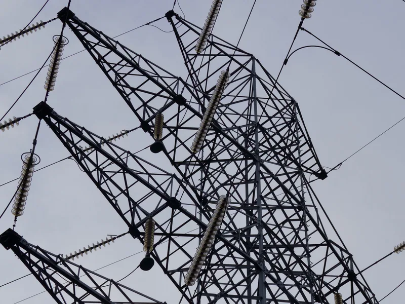
Procurement engineers are highly encouraged to request a custom engineering design consultation to audit switchboard layout drawings and configure the optimal CNC machinery setup.
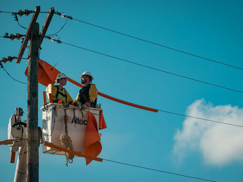
North American switchboard teams can continue with the UL 891 busbar requirements and fabrication guide. To close the assembly loop, use the busbar joint contact-resistance, torque and plating guide to define evidence for connection quality.
Frequently Asked Questions (FAQs)
How does the busbar creepage distance in high-voltage cabinets affect mechanical layouts?
IEC 61439-1 dictates exact air clearances and creepage gaps based on rated insulation voltages. To prevent short-circuit flashovers, structural spacing must exceed 14mm in standard 1,000V cabinets, requiring extreme coordinates precision during CNC copper punching.
What is the recommended joint contact preparation for high-conductivity switchboards?
Copper joints must be punched with sharp, burr-free dies (under HRC 60) to ensure a flat interface. Electro-tin plating (8–12 microns) is applied to prevent oxidation, and joints are locked with belleville spring washers to maintain constant contact tension.
DHCNC-BP-60 CNC Punching & Shearing Workstation
Discover details, parameters, standard dies packages, and factory quotes.