
Copper vs. Aluminum Busbars: Conductivity, Heat Dissipation, and Bending Physics
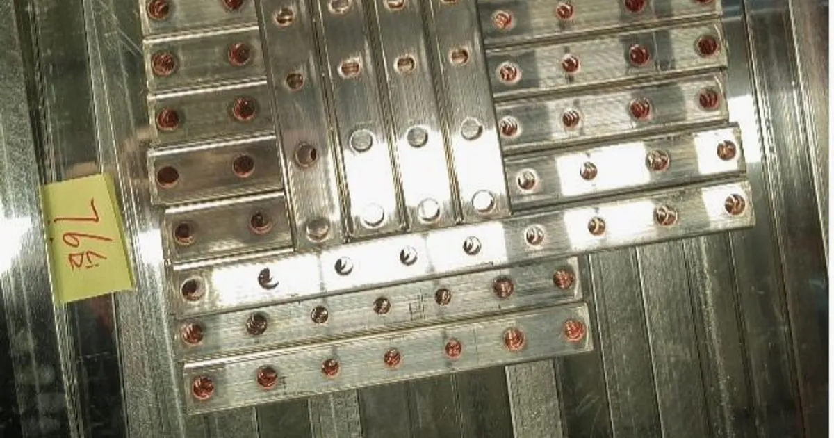
In mid-voltage (MV) and low-voltage (LV) electrical engineering, selecting the optimal conductor material represents a critical design decision. For switchgear assembly, power transformers, and heavy-duty busduct systems, the debate between Copper (Cu) and Aluminum (Al) centers on a trade-off between material costs, physical space constraints, weight limits, and machining requirements.
While copper remains the industry benchmark for high-current applications, aluminum has gained significant market share due to its lightweight profile and lower price per ton. However, substituting these metals is not a direct one-to-one swap. Aluminum requires a larger physical profile and exhibits distinct mechanical properties that demand specialized 3-in-1 multi-station busbar processing equipment or high-precision servo-hydraulic busbar bending machine setups to process without structural failures.
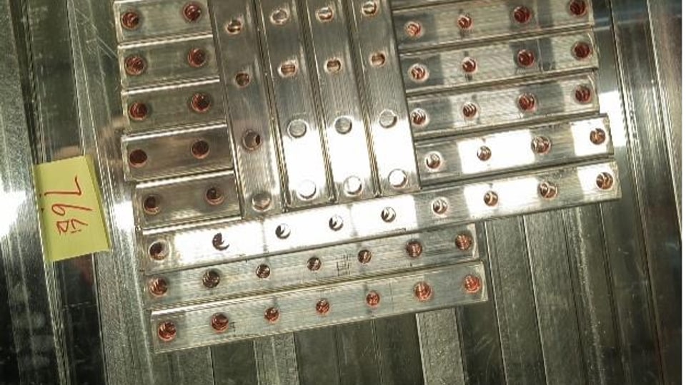
1. Electrical Conductivity & Ampacity Comparison
Electrical conductivity is measured against the International Annealed Copper Standard (IACS), where pure annealed copper is defined as 100% IACS ($58.0 \text{ MS/m}$ at $20^\circ\text{C}$).
Aluminum alloys used for electrical conductors (primarily Grade 6101 or 1350) have a conductivity of approximately 61% IACS ($35.5 \text{ MS/m}$). Consequently, to carry the same current load without exceeding standard temperature rise limits (typically $50^\circ\text{C}$ rise under IEC 61439-1), an aluminum busbar must have a 64% larger cross-sectional area than a copper alternative.
Cross-Sectional Equivalence Formula:
$$A_{\text{Al}} = A_{\text{Cu}} \times \sqrt{\frac{\sigma_{\text{Cu}}}{\sigma_{\text{Al}}}} \approx A_{\text{Cu}} \times 1.64$$
Where:
- $A$ = Cross-sectional area ($\text{mm}^2$)
- $\sigma$ = Electrical conductivity ($\text{MS/m}$)
Electrical & Physical Property Matrix:
| Technical Property | T2 Red Copper (99.90% Cu) | 1060 / 6101 Electrical Aluminum | Engineering Consequences |
|---|---|---|---|
| Electrical Conductivity | 58.0 MS/m (100% IACS) | 35.5 MS/m (61% IACS) | Aluminum requires a larger cross-section |
| Density | $8.92 \text{ g/cm}^3$ | $2.70 \text{ g/cm}^3$ | Aluminum is 70% lighter for equal volume |
| Equivalent Weight Ratio | 100% (Base Reference) | 48% | Aluminum halves the conductor mass for equal amps |
| Tensile Strength | $220 - 320 \text{ MPa}$ | $80 - 150 \text{ MPa}$ | Copper has higher resistance to short-circuit stress |
| Thermal Expansion Coeff. | $16.5 \times 10^{-6}/\text{K}$ | $23.1 \times 10^{-6}/\text{K}$ | Aluminum expands 40% more, stressing bolted joints |
2. Thermal Expansion & Bolted Joint Integrity
One of the most critical challenges in aluminum busbar systems is managing thermal expansion. Aluminum expands and contracts approximately 40% more than copper over identical temperature cycles.
In a bolted busbar joint, this expansion can trigger a destructive cycle known as joint relaxation:
- Under high load, the aluminum bar heats up and expands.
- Because steel bolts expand less, they compress the expanding aluminum beyond its low yield point, causing plastic deformation.
- When the load drops and the system cools, the deformed aluminum shrinks back, leaving a loose joint with high contact resistance.
- The increased resistance generates additional heat under subsequent loads, leading to rapid thermal runaway and arc flash hazards.
To mitigate this, switchgear engineers utilize Belleville spring washers to accommodate expansion and specify strict torque profiles. Prior to installation, all joint interfaces should be processed on a dedicated 3-in-1 busbar processing machine to ensure flat, burr-free contact planes, followed by a high-quality electro-tinning surface treatment to eliminate oxidation layers.
3. Machining & Tooling Differences: Shearing and Punching
Processing copper and aluminum on a CNC machine highlights distinct metallurgical behaviors:
A. Copper Shearing and Punching
Copper is highly ductile but heavy. It requires high shearing forces but cuts cleanly when utilizing professional tools machined from vacuum-hardened Cr12MoV tool steel. Because of its density, maintaining precise die clearances is essential to prevent edge deformation and micro-cracking.
B. Aluminum Shearing and Punching
Aluminum is softer and more “gummy.” During high-speed coordinate punching on a CNC busbar punching shearing machine:
- Material Adhesion: Aluminum particles can adhere to the punch tip, leading to galling and premature tooling wear.
- Burr Generation: If die clearance is too wide, the soft aluminum shears with a substantial burr. This burr reduces dielectric spacing, violating safety codes.
- Custom Tooling: Standard die clearances designed for copper ($8%$ to $10%$ of material thickness) must be widened to $12%$ to $15%$ when processing thick aluminum plates. Specialized lubricants are also required to prevent adhesion.
4. Bending Physics & Elastic Springback Dynamics
Bending copper vs. aluminum highlights substantial mechanical differences. Aluminum has a lower modulus of elasticity ($69 \text{ GPa}$ vs $117 \text{ GPa}$ for copper), which translates to higher elastic springback.
When forming a 90° bend on an aluminum busbar:
- The outer fibers experience high tension, and soft aluminum alloys are prone to micro-fracturing or cracking if the bend radius is too sharp.
- The minimum permitted bend radius for aluminum is generally 1.5 to 2.0 times the bar thickness ($R \ge 1.5t$), whereas copper can often be bent tightly at a $1.0t$ radius.
- The elastic recovery (springback) is highly sensitive to slight material hardness changes.
Utilizing a high-performance horizontal bender with closed-loop servo-hydraulic feedback (such as the DHAC-BB-H Servo-Hydraulic Bending Machine) is vital. The system’s optical encoders and pressure transducers measure real-time material resistance, allowing the Siemens PLC to dynamically adjust the over-bending angle to achieve an exact ±0.2° precision regardless of whether copper or aluminum is processed.
5. Procurement Decision Framework
For compact switchgear cabinets, EV battery modules, and high-density substations, copper busbars remain irreplaceable due to their compact profile and reliable contact interfaces. However, for long-run industrial busduct systems and mass-sensitive power distribution networks, aluminum busbars offer a massive weight and cost reduction, provided that joints are pre-engineered with Belleville washers and materials are processed on high-precision CNC machinery.
Panel manufacturers are invited to request a custom engineering layout consultation to audit their current electrical layout and determine the optimal machinery configuration for their target materials.
Frequently Asked Questions (FAQs)
Why is copper preferred over aluminum in high-load industrial switchgear?
Copper features a significantly higher electrical conductivity (58 MS/m for T2 red copper vs 35.5 MS/m for 6060 aluminum). This allows copper busbars to carry identical ampacity with a 40% smaller cross-section, which is vital for space-constrained switchboard enclosures.
How do you prevent galvanic corrosion when joining copper and aluminum busbars?
To prevent galvanic corrosion at the copper-to-aluminum interface, engineers must use bi-metal transition plates (typically friction-welded copper-aluminum pads) or apply a continuous electro-tinning surface plating layer (at least 8-12 microns) to both contact zones.
DH303-8P 3-in-1 CNC Busbar Processing Machine
Discover details, parameters, standard dies packages, and factory quotes.