
IEC 61439-1 Creepage and Clearance Standards: Mechanical Busbar Layout Guidelines
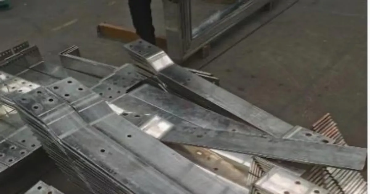
In mid-voltage (MV) and low-voltage (LV) electrical switchgear panel engineering, complying with dielectric insulation standards is the primary safety requirement. When designing high-amp busbar layouts, engineers must calculate and enforce strict physical gaps between phase conductors and grounded metallic planes. Non-compliance leads to severe flashover arcs, equipment destruction, and extreme fire hazards.
To ensure compliance under industrial load profiles, panel builders must transition from manual calculations and basic manual tools to an integrated CNC punching and shearing center or a high-performance 3-in-1 multi-station busbar processor capable of executing highly precise coordinates cuts.
This technical reference paper analyzes the calculations and standards governing Clearance (Air Gaps) and Creepage (Surface Paths) under IEC 61439-1.
Creepage vs. Clearance: Definition of Dielectric Gaps
- Clearance (Distancia de Aislamiento en Aire): The shortest physical distance in air between two active conductive parts (or between a conductor and a grounded metal frame). It governs the machine’s resistance to transient overvoltage spikes (such as lightning or switching surges).
- Creepage (Distancia de Fuga): The shortest distance along the surface of a solid insulation material between two conductors. It prevents slow dielectric tracking and carbonization paths caused by dust, humidity, and pollution over time.
Clearance Air Gap Calculations
Under IEC 61439-1, clearance gaps are determined based on the Rated Impulse Withstand Voltage ($U_{\text{imp}}$) and the Pollution Degree of the operating environment (typically Class 3 for industrial cabinet environments).
To help panel designers verify their layouts, our engineering team has aggregated the minimum clearance requirements:
| Rated Impulse Voltage ($U_{\text{imp}}$) | Minimum Clearance Air Gap (Case A - Inhomogeneous Field) | Minimum Clearance Air Gap (Case B - Homogeneous Field) | Recommended Inspection Coordinates |
|---|---|---|---|
| 4.0 kV | 3.0 mm | 1.5 mm | Direct phase-to-ground |
| 6.0 kV | 5.5 mm | 3.0 mm | Main circuit breaker terminal |
| 8.0 kV | 8.0 mm | 4.5 mm | Principal busbar run supports |
| 12.0 kV | 14.0 mm | 8.0 mm | Substation busduct joints |
Note: B2B electrical enclosures are classified as Case A (inhomogeneous fields) to account for sharp edges, bolt heads, and tooling micro-burrs.
Creepage Surface Path Calculations
Creepage distances are calculated based on the Rated Insulation Voltage ($U_i$), the Pollution Degree, and the Comparative Tracking Index (CTI) of the structural insulation spacers (categorized from Material Group I to IIIa).
For an industrial environment with Pollution Degree 3 and standard Material Group II support blocks ($400 \le \text{CTI} < 600$), the creepage thresholds are:
| Rated Insulation Voltage ($U_i$ - AC or DC) | Creepage Distance (Material Group I) | Creepage Distance (Material Group II) | Creepage Distance (Material Group III) |
|---|---|---|---|
| 250 V | 2.5 mm | 3.6 mm | 5.0 mm |
| 500 V | 5.0 mm | 7.1 mm | 10.0 mm |
| 690 V | 6.9 mm | 10.0 mm | 14.0 mm |
| 1,000 V | 10.0 mm | 14.3 mm | 20.0 mm |
Structural Spacing Enforcement during Manufacturing
To prevent creepage tracking failures, designers install ribbed or corrugated glass-fiber support blocks that artificially lengthen the surface path. Every mounting hole punched into the copper bar must maintain standard margins:
- Minimum distance from a punched hole edge to the edge of the copper plate must exceed 1.5 times the copper thickness ($d \ge 1.5t$).
- Coordinates precision must be locked. A positioning deviation of just 0.5mm on a manual press can compromise the minimum 8.0mm air gap, violating IEC 61439-1.
Utilizing a high-precision servo-hydraulic busbar bending machine ensures bent components maintain exact spatial coordinates with an angular repeatability of ±0.2°, eliminating mechanical alignment drift.
Direct Factory Support & Regional Grid Customizations
Exporting high-voltage switchgear components processing machinery requires pre-engineered compliance with local industrial electrical codes. We pre-calibrate and stress-test all custom-wound motors and proportional valves to handle:
- 220V / 440V - 60Hz (Mexico & Latin America)
- 480V - 60Hz (North America)
- 380V / 400V - 50Hz (Europe, Middle East, Asia)
Panel manufacturers are highly encouraged to request a custom engineering layout consultation to audit switchboard drawings and verify tooling clearance parameters prior to machinery sourcing.
Frequently Asked Questions (FAQs)
What is the minimum air clearance gap required for a 1,000V switchboard under IEC 61439-1?
For low-voltage cabinets operating up to 1,000V AC with a rated impulse withstand voltage (Uimp) of 8 kV, the minimum clearance air gap is 8.0 mm. This must be strictly maintained under all dynamic load stress states.
How does coordinates punching precision affect electrical insulation compliance?
Every punched hole or slot reduces the physical air path. Utilizing a high-precision CNC busbar punching machine ensures coordinates positioning repeatabilities of ±0.15mm, keeping clearances within compliance.
DHCNC-BP-60 CNC Punching & Shearing Workstation
Discover details, parameters, standard dies packages, and factory quotes.