
Busbar Flatness Tolerance: Specify and Inspect Contact Surfaces
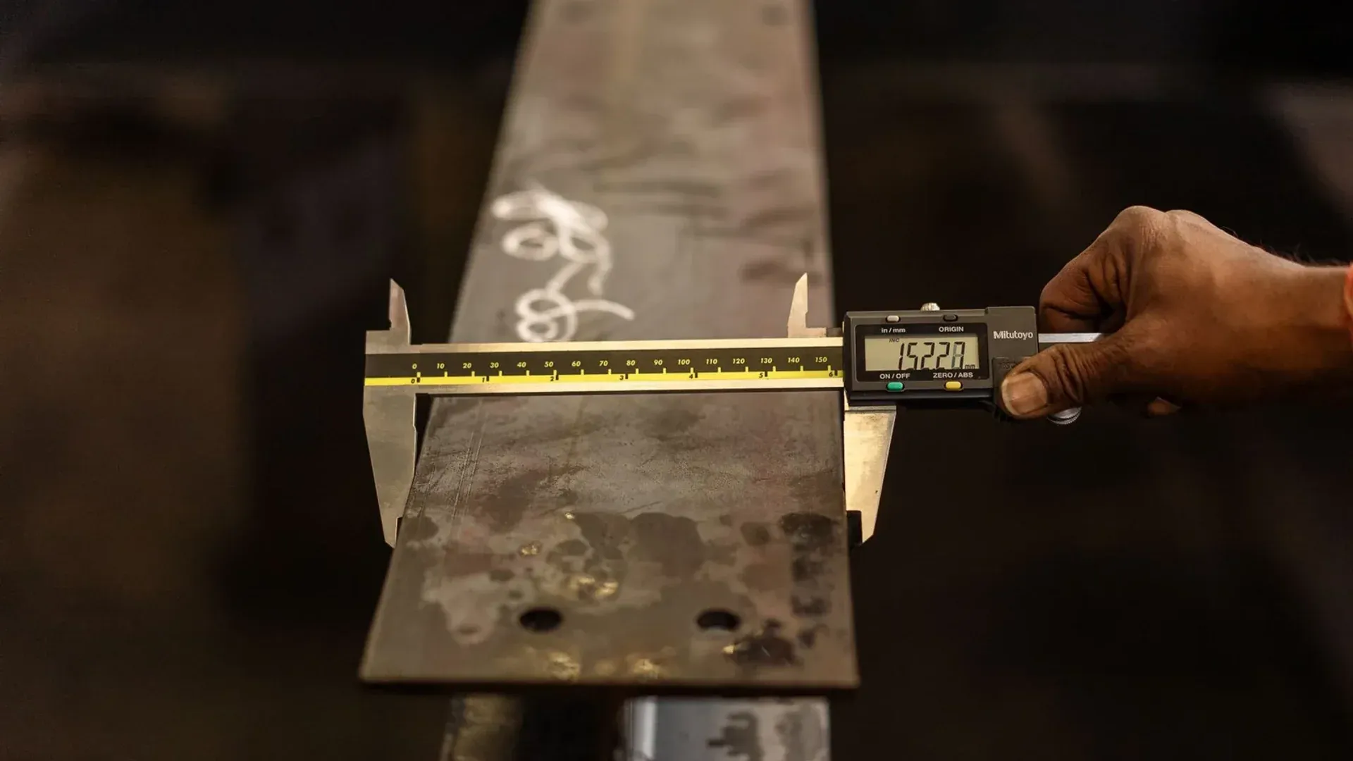
A busbar flatness tolerance is useful only when it identifies the controlled surface, the free or restrained condition, the support points, the measurement method and the acceptance rule. “Keep the busbar flat” can refer to a local contact pad, the long bar, two opposite faces or the gap after bolting. Those are different requirements and should not share one undefined number.
For switchgear and power assemblies, the functional question is whether the fabricated conductor presents the required geometry to its joint, support and enclosure without being forced into place.
Distinguish four different geometry controls
Flatness is a surface form control. It does not need a datum by itself, because it evaluates how the surface lies between two parallel planes. Production drawings often need additional controls for the features around that surface.
| Requirement | What it controls | Typical use |
|---|---|---|
| Local surface flatness | One defined pad or face | Bolted or plated contact area |
| Straightness | A line element or derived axis | Long edge, centreline or bar alignment |
| Parallelism | Orientation of one surface relative to a datum | Opposite faces or assembled interfaces |
| Assembly gap | Result under a defined assembly condition | Joint fit, support contact or enclosure alignment |
A bar can pass local pad flatness and still curve along its length. It can also lie flat on a table while failing a free-state requirement because its own weight or a clamp forces it into contact.
Use the drawing tolerances and datums guide to coordinate flatness with hole position, bend location and assembly datums.
Define the measurement condition before the instrument
State whether the part is measured free, supported at specified points or held in a functional fixture. A long, thin conductor is sensitive to support. Too many support points can hide distortion; too few can let gravity dominate the result.
Document:
- measurement temperature or stabilization requirement when the tolerance justifies it;
- the exact surface area, excluding or including edge-break regions as defined;
- support-point number and location;
- whether plating, coating or insulation is present;
- cleaning method and how burrs or particles are handled;
- whether any clamp force is permitted.
The reference itself must be suitable. A surface plate is a calibrated measurement reference, not merely a heavy table. A technical comparison available through the U.S. Office of Scientific and Technical Information describes surface-plate calibration methods, reinforcing the need to control the reference before interpreting a small part deviation.
Select a method that matches the requirement
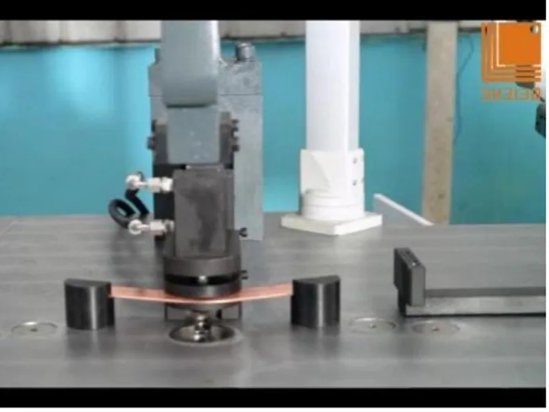
Surface plate and indicator
Place or support the part as specified, establish the indicator and sweep a defined grid across the surface. The range between the evaluated high and low results can support a flatness assessment when the setup and data reduction are appropriate.
Record point locations rather than only the final maximum. A map helps distinguish a local dent, an overall bow and a support-related pattern.
Straightedge and feeler gauge
A qualified straightedge and feeler gauge can screen gaps along selected lines. The method is fast and practical for shop-floor checks, but it samples only the chosen orientations and depends on seating, cleanliness and feel.
Do not call a few straightedge checks a complete surface map unless the inspection plan specifically defines that acceptance method.
CMM or optical profile measurement
A coordinate measuring machine or suitable optical system can collect a denser surface map and preserve traceable point data. Non-contact equipment can also help with surfaces that are easily marked, although reflectivity, edge behavior and filtering must be validated.
An application overview from KEYENCE on flatness and warpage measurement illustrates the range of profile-based approaches. The equipment choice still needs a measurement-system study on the actual copper surface.
Control common sources of false results
Copper is soft enough for dirt, burrs and damaged supports to matter. Clean the reference and part without altering the surface. Inspect for raised material around holes, sheared edges or identification marks before measuring.
Temperature can change a long conductor’s dimensions, while handling can warm a local area. The effect may be insignificant for a broad shop tolerance and material for a tight, long-part study. The inspection plan should match control effort to functional risk rather than adding ritual conditions to every part.
Other common errors include:
- using a workbench as the reference plane;
- clamping a distorted part until it passes;
- comparing one supplier’s indicator sweep with another’s straightedge result;
- placing support directly under the suspected high point;
- reporting only a pass/fail result with no surface or setup identification;
- measuring on plating debris, protective film or an unremoved burr.
Connect flatness to contact performance carefully
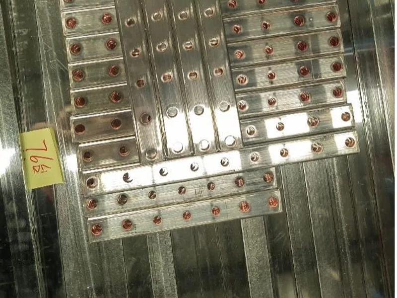
A flatter contact pad can help create a consistent mechanical interface, but flatness alone does not determine electrical contact resistance. Surface finish, plating, cleanliness, joint pressure, fastener system, overlap area and assembly procedure also matter.
Do not convert a contact-resistance requirement into an arbitrary flatness number without validating the joint. The contact-resistance guide explains the other variables that belong in the verification plan.
For a switchgear part, inspect the free-state geometry first and then verify the defined joint or assembly condition. Record any force required to bring the interfaces together. If a joint passes only because bolts pull a severely distorted bar into place, the assembly may carry unintended stress even when an electrical test initially passes.
Write the requirement so two inspectors agree
A complete drawing note or inspection instruction should answer five questions:
- Which surface or bounded area is controlled?
- Is the part free, supported or functionally restrained?
- Where are the support or fixture points?
- Which instrument, scan pattern and evaluation method are used?
- What result is recorded and what happens after a failure?
Include the drawing revision, part orientation and surface condition in the record. If a rough shop-floor method is used for production screening and a CMM or optical method is used for disputes, define their relationship before a disagreement occurs.
The broader finished-busbar inspection checklist can then place flatness alongside material, dimensions, edges, holes, bends, finish and identification.
Verify the process, not only the final number
When flatness fails, trace the result back through cutting, punching, bending, support, deburring, plating and storage. A machine trial should include the actual material size and support arrangement. Inspect the part after release and after relevant downstream processes, because residual stress or handling can change the surface condition.
For switchgear busbar production, make the functional surface and inspection setup part of the sample drawing supplied with the equipment inquiry. That lets the machine builder demonstrate a relevant part and gives purchasing a result that can be reproduced at the buyer’s plant.
Frequently Asked Questions (FAQs)
How is copper busbar flatness measured?
For a controlled inspection, support the cleaned part in the specified free-state condition and sweep the defined surface against a qualified reference using an indicator, CMM or optical system. Record the measurement area, support points, instrument and evaluation rule.
Can a straightedge and feeler gauge verify busbar flatness?
They can provide a practical gap screen along selected lines, but they do not normally map the complete surface flatness zone. Use them only when the drawing or inspection plan defines that method and its limitations.
Is busbar flatness the same as straightness?
No. Flatness controls an entire surface, while straightness controls a line element or axis. A long bar can have acceptable local contact-pad flatness and still fail a separate lengthwise straightness requirement.
What flatness tolerance should a busbar contact surface have?
There is no universal value for every busbar. Set it from joint design, contact area, surface treatment, assembly load and verification method, then confirm that the fabrication and inspection processes can hold it without forcing the part.