
Copper Busbar Shearing vs Saw Cutting: Select by Edge and Throughput
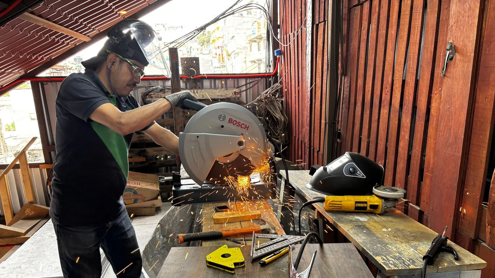
Choose copper busbar shearing when fast straight cuts, compact integration and the absence of a saw-width kerf are valuable and the resulting edge can meet the downstream requirement. Choose saw cutting when the material section, end geometry or finish requirement makes a slower chip-producing cut worthwhile. Neither method should be accepted from a generic “smooth” or “burr-free” claim.
The decision belongs in the process plan because the cut end becomes a datum, bend reference, contact area or visible finished feature in later operations.
Understand what each process does to the edge
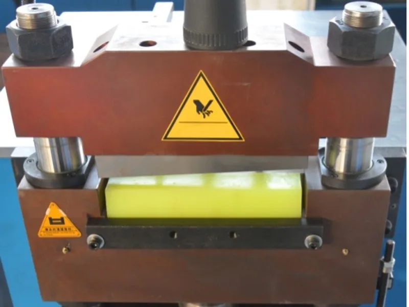
A shear separates the bar by forcing material between two cutting edges. The cut develops rollover near entry, a burnished zone, a fractured zone and a burr near exit. General cutting and shearing guidance from AHSS explains how clearance and tool condition influence these regions. Its examples focus on sheet steels, so the mechanism is useful but copper-specific acceptance must still come from a copper sample.
A saw removes material along the blade path. It creates a kerf and chips, and its end condition depends on blade type, tooth geometry, feed, support, lubrication and material. Saw cutting may reduce the pronounced rollover and fracture pattern of a poor shear, but it can introduce tooth marks, heat, chip contamination or out-of-square cuts.
Do not reduce the comparison to “shear is rough” and “saw is clean.” A well-maintained shear can produce a controlled production edge, and a poorly supported saw can produce an unacceptable end.
Compare the requirements that affect total process time
| Decision factor | Shearing | Saw cutting |
|---|---|---|
| Material removed at cut | No continuous blade-width kerf | Blade-width kerf becomes chips |
| Typical motion | Short force-driven separation | Progressive tooth engagement |
| Edge signature | Rollover, burnish, fracture and possible burr | Saw marks and possible exit burr |
| Housekeeping | No loose saw chips from the cut | Chip collection and cleaning required |
| Production rhythm | Often suited to repeated straight cuts | Often slower but flexible across sections and cut conditions |
| Key controls | Blade clearance, sharpness, alignment and hold-down | Blade selection, feed, support, lubrication and chip removal |
Add downstream time. A fast cut that needs extensive edge correction may not be the faster route. A slower saw that creates chips near a protected contact surface may add cleaning and inspection work.
The busbar deburring guide explains how to control later edge finishing without damaging contact faces.
Let the downstream feature decide the edge requirement
Define what the cut end does in the finished product.
- If it becomes a free non-contact end, a controlled burr and edge-break requirement may be sufficient.
- If it locates the part for later punching, squareness and length consistency may dominate.
- If it becomes a joint or contact interface, flatness, cleanliness and surface preparation need explicit control.
- If it is bent close to the end, distortion and edge cracking risk may affect forming.
- If it will be plated or insulated, sharp edges and embedded chips can create later defects.
Do not specify a cosmetic finish where a functional one is needed. Conversely, do not pay for a precision sawn end if the next operation deliberately removes or machines it.
Include clamping and remnants in the yield comparison
Shearing avoids a saw-width kerf, but the complete nesting still needs material for gripping, positioning and stable end cuts. A machine may also require a minimum tail that cannot be processed automatically. Sawing creates kerf on every cut and may need its own clamp length and trim allowance.
Run the same part list through both proposals. Record starting stock, finished good length, reusable remnants, planned trim, kerf or cut loss, and rejected material. Do not compare one supplier’s best-case nesting with another supplier’s conservative production plan.
For a CNC punch-and-shear route, ask how the software accounts for the shear line, clamp zone and remaining stock. The DHCNC-BP-60 product page should be used to screen the workpiece envelope and available process, while the buyer sample establishes actual edge and yield.
Check distortion and support
A shear applies a high localized force. If clearance, blade condition, hold-down or support is unsuitable, the end may twist, bow or show an excessive burr. A saw applies a different load over a longer time; inadequate support can still let a long bar vibrate or move out of square.
Inspect the part in a free, documented support condition. Do not force the cut end flat against a table and record only length. Check end squareness, local distortion and the long bar’s straightness where those features affect later locating or assembly.
The support used during the trial should match the offered machine. A sample cut on a short coupon does not validate a six-metre stock-handling arrangement.
Run a controlled sample comparison
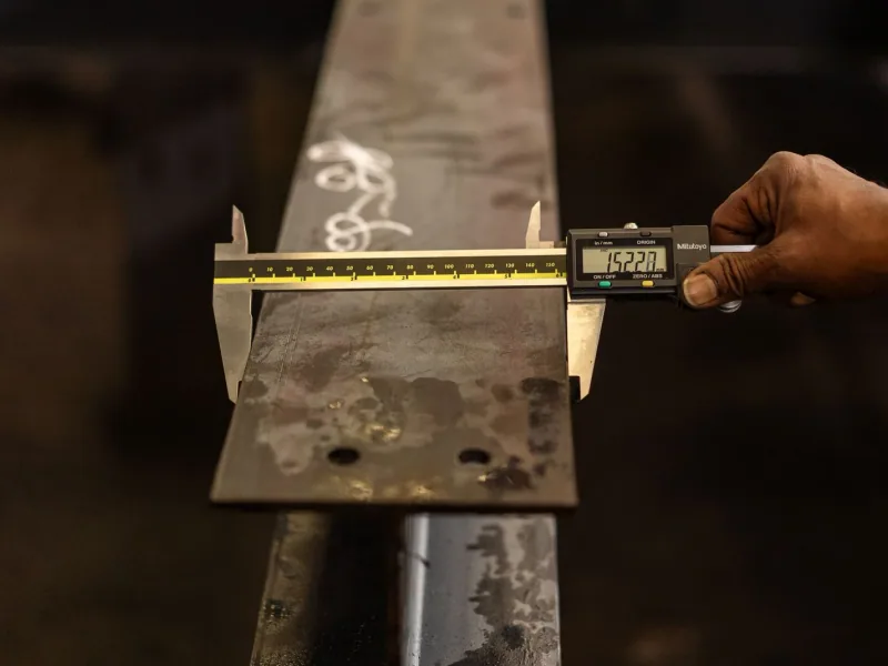
Use the same material lot, widths, thicknesses and target lengths. Include a new or documented stable tool condition, then repeat enough cuts to observe consistency rather than inspecting only the first piece.
Measure:
- finished length and end squareness;
- visible edge zones and maximum burr at defined locations;
- local bow, twist or contact-surface damage;
- process time including load, cut, unload and required cleanup;
- tool setup and change time;
- chips, offcuts and reusable remnant length;
- time required for deburring, cleaning and final inspection.
Use the finished-busbar inspection checklist to connect the cut result to later release requirements.
Write a cutting-machine requirement that can be accepted
For shearing, state material range, cross-section, blade and hold-down arrangement, minimum processable remnant, required edge inspection, tool-maintenance method and replacement scope. For sawing, add blade specification, kerf assumption, feed range, lubrication, chip collection and cleaning responsibility.
Ask the supplier to identify conditions that require a secondary finish. If the process is integrated with punching or bending, demonstrate the complete sequence and confirm that the cut does not change the downstream datum or damage a protected surface.
Use the CNC busbar machine selection guide to place the cutting decision within the wider part-family route. For transformer and busduct work, the heavy-copper workflow guide adds long-part handling and bend-access requirements that may change the choice.
Frequently Asked Questions (FAQs)
Is shearing or saw cutting better for copper busbars?
Shearing is usually attractive for fast straight cuts with no saw-width kerf or loose chips, while sawing can suit thick sections or end-quality requirements that justify a slower chip-producing process. The correct choice depends on the actual material, edge requirement and downstream route.
Can a busbar shear produce a completely burr-free edge?
Do not specify a universal zero-burr claim. A sheared edge contains rollover, burnished and fractured regions, and its burr depends on blade clearance, sharpness, material and support. Define an inspection limit and verify it on production material.
Does saw cutting waste more copper than shearing?
Sawing removes a blade-width kerf, while shearing does not create the same continuous kerf. Both processes can still require lead and tail remnants, clamp allowance and rejected material, so compare measured yield on the same nesting and stock plan.
What should be inspected after cutting a busbar?
Inspect finished length, end squareness, visible rollover or burr, distortion, surface damage and cleanliness. Add a functional check if the end becomes a contact interface or datum for later punching, bending or assembly.
DHCNC-BP-60 CNC Punching & Shearing Workstation
Discover details, parameters, standard dies packages, and factory quotes.